DIY Solar Ground Mount IntegraRack Review
Step-by-step DIY solar ground mount installation using the IntegraRack IR-15 and AnchorSpike system — no concrete pad required. Real-world review from South Florida one year later, including wiring in series, shading lessons learned, and hurricane prep.
Why I Installed a Solar Ground Mount
My garage doubles as a gym and workshop, and South Florida summers are brutal — think 95°F outside, climbing to 105°F inside a concrete block garage. After deciding to add a solar-powered mini split AC to make the space usable year-round, I needed a DIY solar ground mount to power it.
I looked at roof-mounted panels first, but my roof has limited unshaded south-facing space, and drilling into a roof in hurricane country felt like trading one problem for another. A backyard solar ground mount let me pick the exact right spot, keep the roof intact, and angle the array correctly without a roofing contractor.
That decision led me to the IntegraRack IR-15 — an aluminum ground mount system with an AnchorSpike anchoring method that doesn't require pouring a concrete pad or ballast material to keep the solar panels from blowing away. In this article I'll walk through the IntegraRack BallastRack installation step by step, cover the wiring that the video doesn't, and share what I've learned after living with it for about a year.
What Is the IntegraRack IR-15?
The IntegraRack IR-15 is a modular aluminum solar panel ground mount system with a fixed 15° tilt angle. Each module is one frame section, so for four panels in a row you need five modules — one for each panel plus one for the far end.
The key specs that made me choose it:
- Wind rating: Up to 200mph depending on panel size and attachment method — meaningful in Florida
- Storm position: The back legs adjust to drop from 15° to 0°, reducing wind uplift during high-wind events
- AnchorSpike system: Hollow barbed spikes driven into the ground and filled with epoxy — no concrete pad needed
- All aluminum construction: Corrosion-resistant, which matters in coastal South Florida
- 1-inch EMT conduit: Threads through the frames for lateral stability across the whole rack
Other models in the IntegraRack line worth noting:
- IR-30: 30° fixed tilt (better for northern latitudes with lower sun angles)
- IR-35A / IR-45ASA: Adjustable angle — ideal if you want to optimize for seasonal sun angle changes
At 15°, I'm a bit below the ideal tilt angle for South Florida (roughly 24–26°), but that trade-off comes with a lower wind uplift profile — a reasonable compromise for hurricane-prone areas. IntegraRack has their IR-15 engineering and data sheet posted with the wind ratings for the different attachment methods: AnchorSpike, EarthBallast, and concrete pad bolted.
Why I Chose the IntegraRack Hurricane-Rated Solar Ground Mount
Ground mount racking options range from cheap imported aluminum to DIY steel builds to commercial ballast systems, and not all of them make sense for Florida. Here's what pushed me toward the IntegraRack:
- 0° storm position — The IR-15 back legs adjust to drop the panels flat. No other consumer ground mount I found offered a purpose-built storm angle. In hurricane country, being able to reduce wind uplift without disassembling the whole array is a meaningful safety feature.
- AnchorSpike vs. ballast — Alternatives like the PowerField PowerRack rely on weighted ballast material to hold the rack down. Sourcing, transporting, and placing that much ballast in a residential backyard is a real logistical headache. The AnchorSpike epoxy system uses the ground itself as the anchor — no ballast required.
- Panel flexibility — The IR-F2 clamps let you slide panels up and down the rails before locking them in, and the system accommodates a range of panel sizes. This made it easy to add a fifth panel later without redesigning anything.
- Heavy-gauge aluminum construction — Budget options like Eco-Worthy use thinner aluminum that visibly bends and flexes. For a permanent outdoor installation in a windy area, that's a non-starter. The IntegraRack frames feel solid and have shown no flex or deformation after a year outdoors.
- Complete hardware kit — The kit ships with the IR-F2 bonding clamps, through-bolts, conduit set screws, and everything else needed to mount the panels and assemble the rack securely. I didn't have to research what connectors and fasteners to buy separately — it was all in the box.
The IntegraRack IR-15 isn't the cheapest option, but for a semi-permanent Florida installation it's the one I'd buy again.
What You'll Need to Install the IntegraRack IR-15
The materials and installation process below apply to all IntegraRack IR models — including the IR-30, IR-35A, and IR-45ASA — the primary difference being the fixed or adjustable tilt angle of each model.
From IntegraRack:
- IntegraRack IR-15 modules (qty = number of panels + 1)
- AnchorSpike ground anchor kit (includes spikes, epoxy, funnel, mixing supplies)
- IR-F2 bonding clamps (included with IR-15 kit)
From the hardware store:
- 1-inch EMT conduit (measured and cut to panel width minus 1 inch on each end, plus two lengths)
- Copper ground wire (keep it away from aluminum to avoid galvanic corrosion)
- Ground rod and clamp
Tools:
- Bosch SDS-Plus Rotary Hammer — the SDS-Plus handled my South Florida limestone and shell mix without issue
- Bosch SDS-Plus bit — carbide tip, 26–30 inch depth
- Bubble level — you'll use this constantly
- 5/8 Ground Rod Driver
- Dewalt nut driver set
- String line and stakes
- Drill (in drill mode only — not impact or hammer for assembly)
- Spray paint for marking hole locations
- A second (or third) person — you'll need help lifting panels
For panel wiring:
- MC4 connectors (if your panels don't have pre-attached leads)
- 20A inline fuse — on the positive string before the isolator to protect the wiring
- DC isolator switch (rated for your string voltage and current)
IntegraRack IR-15 Installation Step by Step
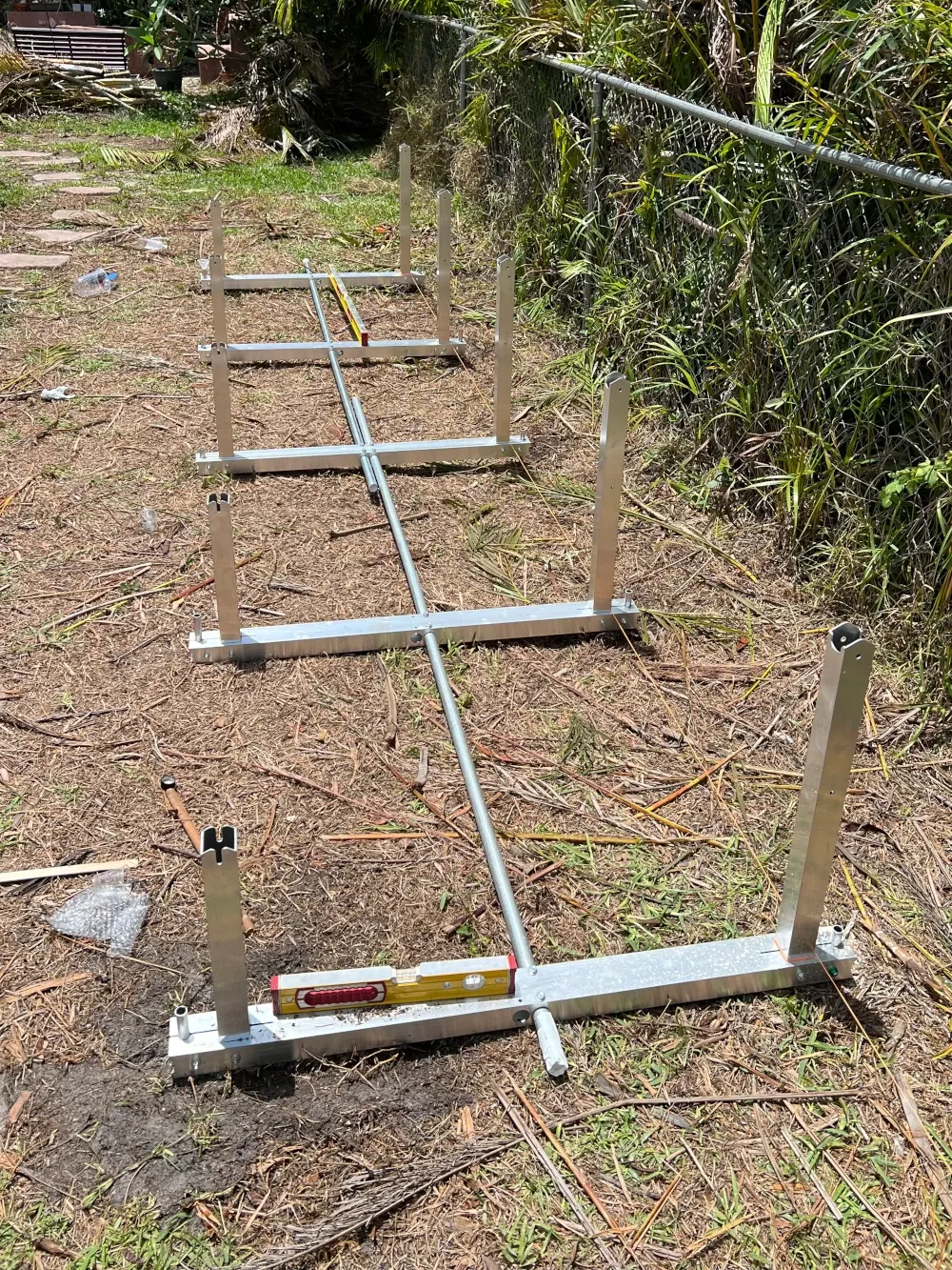
1. Frame Assembly
Each IR-15 module has a long rear leg and a shorter front leg. Assemble each module by connecting the legs and threading the conduit through the frame holes as you work across the row. The conduit is what ties all the modules together laterally — it's not optional.
Spacing matters: Your conduit length inside the frames should equal your panel width minus 1 inch. My Trina 410W panels are 44⅝ inches wide, so I cut to 43⅝ inches of inside spacing. Measure the conduit span, not the post spacing.
Use the included self-tapping conduit screws to lock each frame to the conduit — drill mode only, not hammer or impact mode. Stripping these is easy to do and hard to undo.
Tip: The aluminum edges on the frames may be rough or sharp from machining. Consider wearing tough work gloves as a precaution.
2. Positioning the Solar Array
Before you drill anything, lay the assembled rack in its intended position and spend real time looking at it from multiple angles at different times of day.
I'll say more about shading lessons later, but the short version: check for shadows not just at your installation date, but also imagine where the sun will be in winter. The sun angle in December is significantly lower on the horizon than in June. A location that looks perfect during a summer install can have morning roofline shading in January that you'd never anticipate. The Shade Map tool is handy for visualizing exactly how shadows will track at your location throughout the day and year.
Use a string line to keep the array parallel to your fence line or property boundary. Mark the spike hole locations with a dowel pushed down through the frame holes, then move the rack aside before drilling. Mark the hole centers with spray paint as a backup reference after the dowel marks.
3. Drilling the BallastRack AnchorSpike Anchor Holes
The IntegraRack BallastRack AnchorSpike holes need to go 26–30 inches deep. For most of South Florida's limestone and shell mix, the Bosch SDS-Plus rotary hammer handles this without issue when combined with the Bosch SDS-Plus bit. Some holes will hit a large rock and slow down — keep steady pressure and let the rotary hammer do the work. I hit a few boulders where adding a bit of water to the hole helped the bit cut through. An SDS-Max would likely be overkill for anything short of solid concrete.
Once drilled, the rack goes back into position and the spikes drop in, barbs pointing down.
4. Leveling the IntegraRack Ground Mount
Before epoxy, get the rack level. This is where having an accurate bubble level is important — check front-to-back and side-to-side on multiple modules. The one I linked is more precise than most and one of my favorite tools I'm glad I spent extra on. The spikes can shift up and down before the epoxy is poured, so this is your window to dial everything in.
Have a helper on the far end while you check level. Take your time here; once the epoxy goes in, it's done.
5. Pouring the AnchorSpike Epoxy
The kit includes two-part epoxy (Part A + Part B), a mixing cup, measuring cup, funnel, stirring stick, and gloves.
- Mix equal parts A and B and stir for 2 minutes. Thorough mixing is what activates the epoxy reaction — don't shortcut this.
- Pour using the included funnel — each spike takes roughly one measured cup
- Working time is 45–50 minutes; in hot conditions expect less working time
- IntegraRack says 8 hours before mounting panels; the product label says 24 hours to cure and 72 hours to fully cure
- The epoxy seeps out through the barbs and side openings, forming what IntegraRack calls "epoxy roots" underground, adding the uplift resistance the system is designed around
Watch the mixing cup for cracks. Mine had a hairline crack before I started — check both cups before mixing so you're not pouring mixed epoxy with a leaking container.
Once the epoxy cures, tighten the uplift bolt-and-washer hardware that clamps the rack frame down onto each spike collar. This is the final mechanical lock against uplift.
6. Grounding
Install your ground rod nearby and run copper ground wire from the rack to the rod. One important note from the IntegraRack instructions: copper ground wire must not touch the aluminum frames directly — galvanic corrosion will occur over time. Use approved bimetallic connectors or a grounding lug at the connection point.
The IR-F2 bonding clamps create electrical continuity between panel frames and the rack structure, so the grounding path flows from panels → rack → ground rod.
Check local requirements for grounding specifics, but the general recommendation I've come across is to use two ground rods spaced 8–10 feet apart rather than one. A single rod may not achieve the target resistance of 25 ohms or less depending on your soil — and since the test equipment to verify that costs more than a second rod, adding one is the practical move.
The 5/8 ground rod Driver attached to the rotary hammer made driving the rods much less work.
7. Mounting the Solar Panels
Stage your panels nearby before lifting — you'll want them close when it's time to set them in position. Pre-attach the IR-F2 clamps loosely to the panel frames at roughly 15 inches from each end (top and bottom) so they're ready to slide onto the rack rails.
You need at least two people to mount panels safely. Four people is better — one on each corner for large panels. Get the panel to height, slide the IR-F2 clamps onto the rail, center the panel in the frame spacing, and snug the clamps to hand-tight while you confirm alignment. Once all panels are positioned and aligned, final-tighten with the included wrench.
Wiring Solar Panels in Series for a Mini Split
The video ends at panel mounting, so here's what comes next — the wiring step that actually makes the array work.
My four Trina 410W panels are wired in series, which means the positive terminal of one panel connects to the negative terminal of the next. Series wiring adds voltage with each panel while keeping the current (amps) the same, which is what the Airspool's MPPT solar input expects.
Here's the wiring path from panels to the AC unit:
┌─────────┐    ┌─────────┐    ┌─────────┐    ┌─────────┐
│ Panel 1 │    │ Panel 2 │    │ Panel 3 │    │ Panel 4 │
│  410W   │    │  410W   │    │  410W   │    │  410W   │
│  +   -  │    │  +   -  │    │  +   -  │    │  +   -  │
└──┬───┬──┘    └──┬───┬──┘    └──┬───┬──┘    └──┬───┬──┘
   │   └──────────┘   └──────────┘   └──────────┘   │
   │                                                │
   │  (+) string                        (-) string  │
   │                                                │
[20A Fuse]                                          │
   │                                                │
   └──────────── [DC Isolator Switch] ──────────────┘
                        │           │
                       (+)         (-)
                        │           │
                 [Airspool MC4 Solar Whips]
The 20A inline fuse goes on the positive string before the DC isolator switch. The DC isolator switch gives you a safer way to disconnect the array from the AC unit for service or storms. From there, MC4 solar whip connectors plug directly into the Airspool's solar input ports.
Route your conduit from the array to the AC unit's outdoor unit using weatherproof conduit and UV-resistant cable. Keep the DC run as short as practical — longer runs increase voltage drop.
I used these 10AWG solar extension cables — they've held up well with solid connectors and UV-resistant jacketing.
One Year Later: Does the Ground Mount Hold Up?
After about a year in South Florida conditions — heat, humidity, intense summer rain, and near-tropical-storm winds — the ground mount has held up exactly as I'd hoped.
What's held up well:
- The array remains perfectly level with no settling
- No rust or corrosion on the aluminum frames
- The AnchorSpike anchors feel solid — no play, no movement
- The whole structure is noticeably rigid; pushing on a corner panel doesn't flex anything
The brown anoles and lizards have enjoyed the new habitat I've created for them as well 🤣
What I added: I had an extra panel sitting idle and discovered the IntegraRack system makes expansion straightforward — I added one more module and panel to the existing array. The established anchor points stayed in place and the new section attached cleanly to the existing conduit run. One note: AnchorSpike kits come in minimum quantities, so adding a single panel later is more expensive than planning for it upfront. Think ahead about what capacity you might want before you order.
Storm position: I've had near-passing tropical storms track close enough to bring high winds, and the array came through without issue at the 15° position. I haven't needed to use the 0° storm position yet, but it's reassuring that it's there.
Solar Shading Lessons Learned
The two biggest lessons learned after installing the solar panels both involve shading. Both were easy to miss during a summer installation.
Lesson 1: Creeping Tree Shadows
When I selected the array location, I verified the panels weren't in direct shade from nearby trees at the time. What I didn't fully account for was how shadow angles shift throughout the day and year. Over time, a tree line to the west started casting an early-afternoon shadow onto the farthest left panel earlier than expected.
The problem is how series wiring responds to shading: when one panel in a series string produces less power due to shade, it acts as a bottleneck and limits the output of the entire string — not just the shaded panel. One partially shaded panel can drop the whole array's output significantly.
My fix was a Tigo TS4-A-O solar optimizer installed inline on the affected panel. The optimizer decouples that panel from the string's constraints, letting the shaded panel produce what it can while the remaining panels continue at full output.
Tigo optimizers are worth considering any time you have:
- Nearby trees with expanding canopies
- Chimneys, poles, or pipes that cast a narrow moving shadow across a panel as the sun tracks
- Any source of partial shading that hits only one or two panels in a series string
The optimizer is a targeted fix — but the real solution is placement. Study shadow patterns before you commit to a location.
Lesson 2: Winter Sun Angle
In South Florida the sun angle at solar noon is about 41° above the horizon in December versus nearly 88° in June. I installed the array in summer and never thought about where the shadows would fall in winter.
Starting in November, the rightmost panels began picking up roofline shade during morning hours — something that simply didn't happen at any point during summer. The roofline was never even close to casting a shadow in June; in December it was blocking the first two hours of morning sun. Fortunately, winter months require less cooling, so the impact was less severe than it could have been — but hopefully this saves you from making the same mistake.
Before finalizing your panel placement: check not just mid-day sun in your installation season, but also simulate early morning and late afternoon, and imagine a sun that's 30–40° lower on the horizon. A location that looks ideal in June may be significantly shaded in December.
The Finished Array: 1,640W+410W of Solar
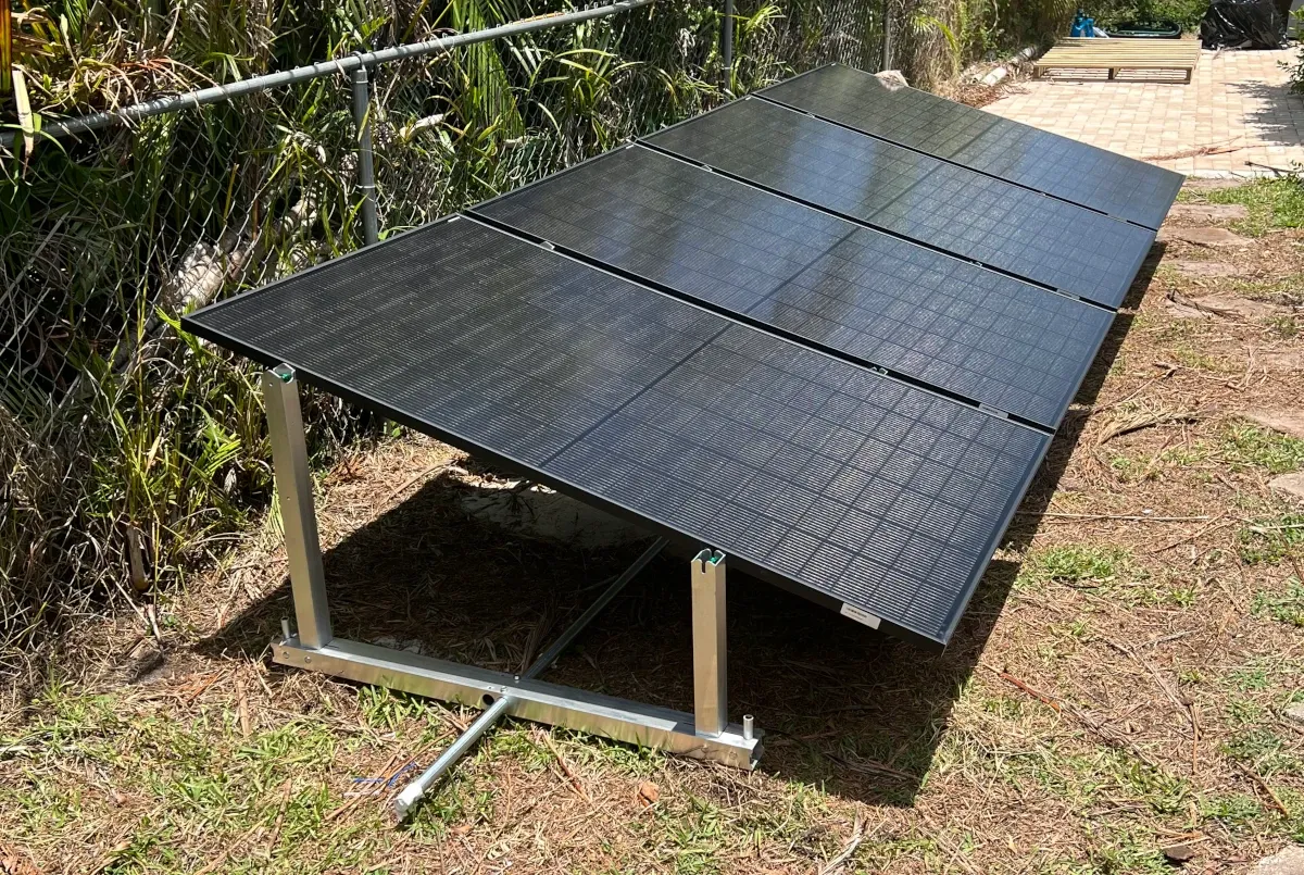
Four Trina 410W bifacial panels = 1,640W peak. The bifacial design means the panels also capture reflected light off the grass below, which adds a few percent to real-world output on bright days. I later added my spare backup panel to bring the array to 2,050W — better performance on overcast days, and better than letting it sit idle.
This array feeds the Airspool hybrid solar mini split directly, with the unit's inverter managing the transition between solar and grid power automatically. On a clear South Florida summer day, the AC runs entirely on solar through most of the day. On cloudy days or at night, it draws from the grid seamlessly to make up for varying solar output.
If you're planning a backyard solar ground mount installation in Florida or another hurricane-prone area, the IntegraRack IR-15 is worth the premium. For a full breakdown of how the Airspool performs on that solar power, what it cost, and the payback math, read the companion article.
If you also have a pool with solar heating collectors, calculating the optimal speed for your variable speed pool pump follows the same South Florida energy-saving logic — find the lowest RPM that meets your flow requirements and run it there.